Category Archives: Electronic Components

Mastering the Chemistry: Hydrofluoric Acid (HF) in PCB Wet Etching

In the world of PCB manufacturing, precision and control are paramount in crafting intricate circuit patterns. One of the most potent and challenging chemical solutions utilized in the wet etching process is Hydrofluoric Acid (HF). Composed of hydrogen and fluorine, HF is a highly corrosive and hazardous acid known for its ability to dissolve various materials, including glass and metals. In this blog, we will delve into the specifics of Hydrofluoric Acid (HF) and provide valuable details on its technique for use in PCB wet etching machines, emphasizing safety and precision.

In the field of chemistry Hydrofluoric Acid belongs to which category?

Inorganic Fluxes

Inorganic fluxes are highly corrosive, and are comprised of inorganic acids and salts such as hydrochloric acid, hydrofluoric acid, stannous chloride, sodium or potassium fluoride, and zinc chloride. These fluxes are capable of removing oxide films of ferrous and nonferrous metals such as stainless steel, Kovar and nickel irons, which cannot be soldered with weaker fluxes.

Inorganic fluxes generally are used for nonelectronics applications such as the brazing of copper pipes. They are, however, sometimes used for lead-tinning applications in the electronics industry. Inorganic fluxes should not even be considered for electronics assemblies (conventional or surface mount) because of potential reliability problems. Their major disadvantage is that they leave chemically active residues than can cause corrosion and serious field failures.

Performance criteria for chemical milling


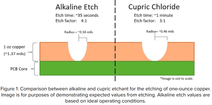
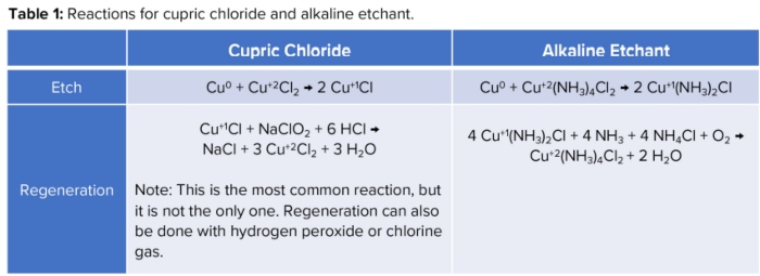
photoresists are in many ways more demanding than those of PWB fabricators; there is aplethora of different substrates such as Alloy 42,beryllium copper, iron-nickel alloys, molybdenum, tungsten, Invar, and many more. Theetching chemistries and etch conditions, which the resist must survive, are brutal. In addition to the more benign cupric chloride and the mainstream ferric chloride, you find mixtures of hydrofluoric and nitric acid which embrittle the resist, as well as very highly alkaline solutions of potassium ferrocyanide, which act like strippers on aqueous processable resists.

What is Hydrofluoric Acid (HF)?

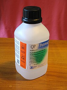
Hydrofluoric Acid (HF) is a strong, colorless liquid acid with the chemical formula HF. Due to its reactivity and corrosiveness, HF is typically used with caution in specialized applications, such as glass etching, metal cleaning, and semiconductor manufacturing. In PCB wet etching, HF is employed to selectively remove silicon dioxide (SiO2) or glass passivation layers from semiconductor devices, enabling the creation of specific circuit patterns.

Hydrofluoric Acid

Technique of Using Hydrofluoric Acid (HF) for PCB Wet Etching:

  1. Preparing the HF Solution:

To prepare the HF etchant solution, dilute the concentrated HF with deionized water to achieve the desired concentration. The concentration of HF is typically expressed in percentage (%). Common concentrations for PCB wet etching are around 5% to 10% HF.

  1. Personal Protective Equipment (PPE):

Safety is paramount when handling HF. Always wear appropriate Personal Protective Equipment (PPE), including acid-resistant gloves, a full-face shield, chemical-resistant apron, and safety goggles to protect against splashes and inhalation of vapors.

  1. Proper Ventilation:

Always work with HF in a well-ventilated area or under a fume hood to prevent exposure to its toxic and corrosive vapors.

  1. Etching Temperature:

The etching temperature can significantly impact the etch rate and selectivity. Typically, HF etching is conducted at room temperature (around 20°C to 25°C) to ensure precision and consistency.

  1. Immersion Time:

The immersion time in the HF etchant solution determines the depth of etching. Longer immersion times result in deeper etching, while shorter times yield shallower patterns. The immersion time should be carefully controlled based on the desired circuit design and the thickness of the SiO2 or glass passivation layer.

  1. Agitation:

Gentle agitation of the etchant solution can promote an even distribution of the HF across the substrate’s surface, ensuring uniform and precise etching results.

  1. Neutralization and Disposal:

HF should not be neutralized with alkaline substances, as this can produce toxic and corrosive fluoride salts. Instead, HF should be treated with specific HF neutralizing agents. After etching, the spent HF solution should be carefully collected and disposed of according to environmental regulations.

Conclusion:

Hydrofluoric Acid (HF) is a powerful tool in PCB wet etching, enabling engineers to achieve precision and control in crafting intricate circuit patterns. By adhering to proper safety protocols and technique, HF can be handled with confidence, and PCB manufacturers can create high-quality and reliable electronic devices. Embrace the chemistry of HF, and elevate your PCB manufacturing process to new heights of accuracy and excellence.

As a wet process engineer, mastering the use of Hydrofluoric Acid (HF) in PCB wet etching empowers you to create cutting-edge electronic devices with flawless circuitry, revolutionizing the world of technology. Happy etching!

Mastering the Art of Cupric Chloride Etchant in PCB Wet Etching: A Step-by-Step Guide

In the realm of printed circuit board (PCB) manufacturing, Cupric Chloride Etchant stands as a powerful ally in achieving precision and control during the wet etching process. This chemical solution, composed of cupric chloride (CuCl2), enables engineers to selectively remove copper from PCB substrates, shaping intricate circuit patterns. In this blog, we will delve into the specifics of Cupric Chloride Etchant and provide valuable tips for its effective utilization in PCB wet etching machines.

What is Cupric Chloride Etchant?

Cupric Chloride Etchant is an acidic solution containing cupric chloride, a chemical compound known for its ability to dissolve copper efficiently. This etchant is widely used in the PCB manufacturing industry for its excellent selectivity, allowing for precise copper removal without adversely affecting other materials on the PCB.

Tips for Using Cupric Chloride Etchant in PCB Wet Etching Machine:

  1. Etchant Preparation:

To prepare the Cupric Chloride Etchant solution, mix cupric chloride crystals with hydrochloric acid (HCl) in a proper ratio. The common ratio is approximately 100 grams of cupric chloride per 100 milliliters of concentrated hydrochloric acid. Always add the acid to the water slowly while stirring, and ensure you’re working in a well-ventilated area with proper safety equipment.

  1. Temperature Control:

Maintaining the right temperature is crucial for achieving accurate etching results. The ideal operating temperature for Cupric Chloride Etchant typically ranges from 35°C to 50°C (95°F to 122°F). Consider using a temperature-controlled wet etching machine to ensure precise regulation.

  1. Immersion Time:

The etching time is directly related to the depth of copper removal. Longer immersion times result in deeper etching, while shorter times yield shallower patterns. The immersion time can vary depending on the desired circuit design and the thickness of the copper layer.

  1. Agitation:

Gentle agitation of the etchant solution can enhance the etching process by promoting even distribution. Proper agitation helps prevent over-etching or under-etching and ensures uniformity across the PCB surface.

  1. Neutralization and Disposal:

After the etching process, neutralize the Cupric Chloride Etchant to ensure it is deactivated and rendered safe for disposal. Utilize a neutralizing agent, such as sodium carbonate (Na2CO3), to neutralize the etchant solution before disposing of it responsibly according to environmental regulations.

  1. Safety Precautions:

Cupric Chloride Etchant is corrosive and toxic, requiring careful handling. Always wear appropriate personal protective equipment (PPE), work in a well-ventilated area, and follow proper safety protocols to avoid accidents and exposure to harmful fumes.

About Cupric and Alkaline
Together, these etchants are used in the majority of PCB etch shops, with alkaline being the most popular. To provide a baseline of how they work, their etch reactions along with their corresponding regeneration reactions, can be found in Table 1.

One of the main reasons these two etchants are the most used is because of their regeneration capabilities. With regeneration, you increase the capacity of copper you can etch. It also helps keep the etch rate at a consistent value. To maintain mass production of PCBs, it is important to keep the etch rate steady but also high enough to maximize output. Since etch rate can greatly influence production rates, it is a major factor when comparing etchants.

https://pcb.iconnect007.com/index.php/article/132406/the-chemical-connection-etchants-of-the-industrycupric-vs-alkaline/132409/?skin=pcb

Etch Factor

Another matter where alkaline etchant is highly favored is etch factor, the ratio of downward etch to sideways etch. Alkaline etchant offers the benefit of a 4-to-1 etch factor (meaning it etches downward four times as much as it etches sideways). Cupric provides a standard 3-to-1 etch factor (Figure 1).

Image from:https://pcb.iconnect007.com/index.php/article/132406/the-chemical-connection-etchants-of-the-industrycupric-vs-alkaline/132409/?skin=pcb

Alkaline etchant’s better etch factor opens the opportunity to maintain finer spaces and line widths when you are etching panels with thicker copper layers. Although alkaline can provide a great etch factor, a 4-to-1 ratio can only be obtained if the etchant is kept at its optimal condition, which is easier said than done.

Mastering the art of Cupric Chloride Etchant in PCB wet etching opens the door to unparalleled precision and control in circuit pattern creation. By adhering to proper etchant preparation, temperature regulation, immersion time, and safety precautions, engineers can craft intricate PCB designs with confidence. Embrace the power of Cupric Chloride Etchant and elevate your PCB manufacturing process to new heights of accuracy and efficiency.

In the realm of printed circuit board (PCB) manufacturing, Cupric Chloride Etchant stands as a powerful ally in achieving precision and control during the wet etching process. This chemical solution, composed of cupric chloride (CuCl2), enables engineers to selectively remove copper from PCB substrates, shaping intricate circuit patterns. In this blog, we will delve into the specifics of Cupric Chloride Etchant and provide valuable tips for its effective utilization in PCB wet etching machines.

Components of Frequency Converters: Exploring Internal Structure


Frequency converters, also known as power converters or frequency changers, are electronic devices used to convert electrical power from one frequency to another. The composition of a frequency converter can vary depending on its specific application and power rating. However, here are the common components found in frequency converters:

  1. Rectifier: The rectifier is responsible for converting the incoming alternating current (AC) power into direct current (DC) power. It typically consists of diodes arranged in a bridge configuration to rectify the AC waveform.
    • Diodes: Rectifiers use semiconductor diodes, typically in a bridge configuration, to convert AC power to DC power. Diodes are made up of semiconductor materials, such as silicon or germanium, with a p-n junction that allows current flow in one direction while blocking it in the reverse direction.
    • Heat sinks: Since rectifiers can generate heat during operation, heat sinks are often attached to diodes to dissipate heat and prevent damage to the components. Heat sinks are made of thermally conductive materials, such as aluminum or copper, with fins to increase the surface area for efficient heat dissipation.
    • How are the Diodes, Heat sinks inside the Rectifier of Frequency Converters made?
  2. DC Link: The DC link is a capacitor bank or an energy storage device that smoothens the rectified DC voltage and provides a stable DC voltage source to the inverter.
    • Capacitors: The DC link uses capacitors to store electrical energy and provide a stable DC voltage source to the inverter. Electrolytic capacitors, with high capacitance values, are commonly used in DC link applications. They are made of two conductive plates separated by an insulating material (dielectric) and are typically enclosed in a cylindrical or rectangular case.
    • How are the Capacitors inside the DC Link of Frequency Converters made?
  3. Inverter: The inverter is a key component that converts the DC power from the rectifier into the desired AC frequency and voltage. It uses semiconductor switches (typically insulated gate bipolar transistors or IGBTs) to generate a high-frequency AC waveform. The inverter’s output voltage and frequency can be controlled to match the requirements of the target application.
    • nsulated Gate Bipolar Transistors (IGBTs): IGBTs are the main switching devices used in the inverter. They are three-terminal devices that combine the advantages of both bipolar junction transistors (BJTs) and metal-oxide-semiconductor field-effect transistors (MOSFETs). IGBTs consist of multiple layers of semiconductors and are controlled by a gate signal to switch on and off, allowing the conversion of DC power to AC power.
    • Gate Driver Circuitry: The gate driver circuitry provides the necessary voltage and current signals to control the switching of IGBTs. It ensures precise timing and synchronization of the switching process to achieve the desired output voltage and frequency.
    • How are the Insulated Gate Bipolar Transistors (IGBTs), Gate Driver Circuitry inside the Inverter of Frequency Converters made?
  4. Filters: Filters are used to reduce harmonic distortion in the output waveform of the inverter. Harmonics are unwanted frequency components that can cause interference or damage to other equipment in the electrical system. Filters can be designed to mitigate these harmonics and provide a cleaner output waveform.
    • Inductors: Filters include inductors to reduce harmonic distortion by filtering out unwanted high-frequency components from the output waveform. Inductors are made of coils of wire wound around a core, which can be air, iron, or ferrite. They store energy in a magnetic field and impede the flow of high-frequency currents.
    • Capacitors: Capacitors are also used in filters to further suppress harmonics and smooth the output waveform. These capacitors are typically connected in parallel with the load or in series with the inductors to form LC (inductor-capacitor) filter circuits.
    • How are the Inductors, Capacitors inside the Filters of Frequency Converters made?
  5. Control System: The control system consists of a microprocessor or a digital signal processor (DSP) that monitors and controls the operation of the frequency converter. It regulates the output voltage and frequency, ensures protection against faults, and provides various control modes and functions.
    • Microprocessor/Digital Signal Processor (DSP): The control system incorporates a microprocessor or DSP that receives feedback signals, executes control algorithms, and generates control signals for regulating the output voltage and frequency. These components consist of integrated circuits (ICs) with complex electronic circuits and computational capabilities.
    • Feedback Sensors: Feedback sensors, such as voltage sensors, current sensors, and temperature sensors, are used to measure various parameters in the system and provide feedback to the control system for closed-loop control.
    • Control Algorithms: Control algorithms are software programs that run on the microprocessor or DSP. These algorithms implement control strategies, such as pulse width modulation (PWM) techniques, to adjust the output voltage and frequency according to the desired specifications.
    • How are the Microprocessor/Digital Signal Processor (DSP), Feedback Sensors, Control Algorithms inside the Control System of Frequency Converters made?
  6. Cooling System: Frequency converters generate heat during operation, and a cooling system is necessary to maintain optimal temperature and prevent component damage. The cooling system may include fans, heat sinks, or liquid cooling methods, depending on the power rating and design of the converter.
    • Fans: Fans are commonly used in frequency converters to provide forced air cooling. They consist of an electric motor and blades that circulate air over heat sinks or other components to dissipate heat.
    • Heat Sinks: Heat sinks are made of thermally conductive materials and are often attached to power electronic components, such as diodes, IGBTs, or other heat-generating elements, to absorb and dissipate heat efficiently.
    • How are the Fans, Heat Sinks inside the Cooling System of Frequency Converters made?
  7. Protection and Safety Devices: Frequency converters incorporate various protection and safety features to ensure reliable operation and protect against faults. These may include overcurrent protection, overvoltage protection, short-circuit protection, thermal protection, and various interlocks.
    • Circuit Breakers: Circuit breakers are electromechanical devices that automatically interrupt the current flow in the event of an overload or short circuit. They consist of a bimetallic strip or an electronic trip unit that responds to excessive current and opens the circuit.
    • Overvoltage Protection Devices: These devices, such as metal oxide varistors (MOVs) or transient voltage suppressors (TVS), protect against voltage spikes or surges that could damage the converter or connected equipment.
    • Temperature Sensors: Temperature sensors are used to monitor the temperature of critical components and trigger protective actions, such as reducing the output power or shutting down the system, in case of excessive heat.
    • How are the Circuit Breakers, Overvoltage Protection Devices, Temperature Sensors inside the Protection and Safety Devices of Frequency Converters made?
  8. Control and Monitoring Interfaces: Frequency converters often have control and monitoring interfaces to enable communication with external systems or user interfaces. These interfaces can include digital communication ports, analog input/output signals, and human-machine interfaces (HMI) such as touchscreens or keypad displays.
    • Digital Communication Ports: Frequency converters may include serial communication ports (such as RS-485, Ethernet, or CAN) to facilitate communication with external systems, such as programmable logic controllers (PLCs) or supervisory control and data acquisition (SCADA) systems.
    • Analog Input/Output Signals: Analog signals, such as voltage or current signals, can be used for control and monitoring purposes. These signals may be used to set the desired output voltage or frequency or to provide feedback on the system’s status.
    • Human-Machine Interfaces (HMI): HMIs provide a user interface for operators to interact with the frequency converter. They can include touchscreens, keypads, displays, and indicators to show system parameters, alarms, and allow configuration adjustments.
    • How are the Digital Communication Ports, Analog Input/Output Signals, Human-Machine Interfaces (HMI) inside the Control and Monitoring Interfaces of Frequency Converters made?